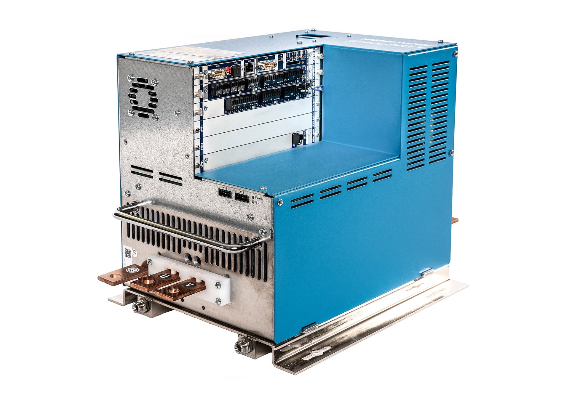
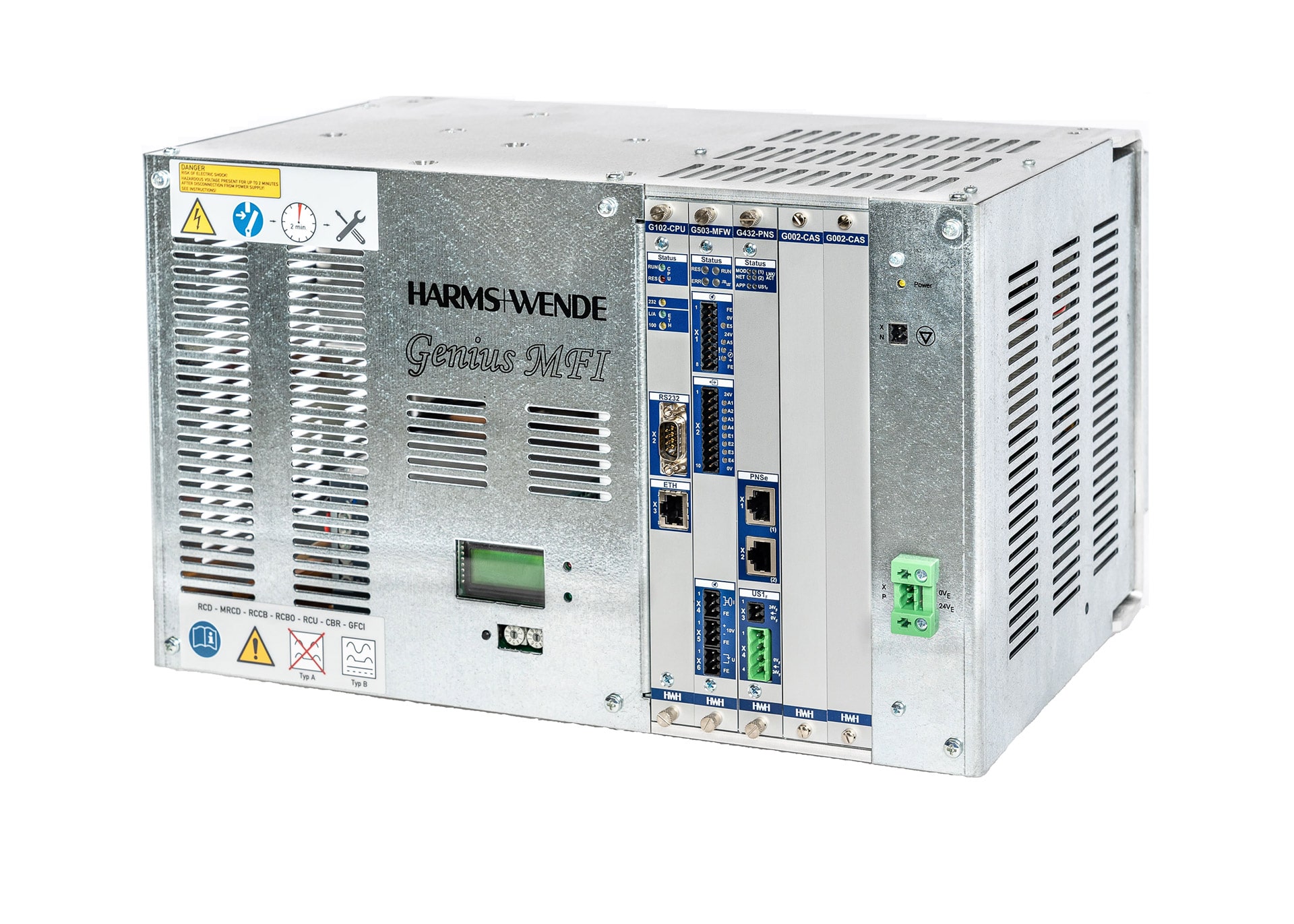
Genius product range
Options
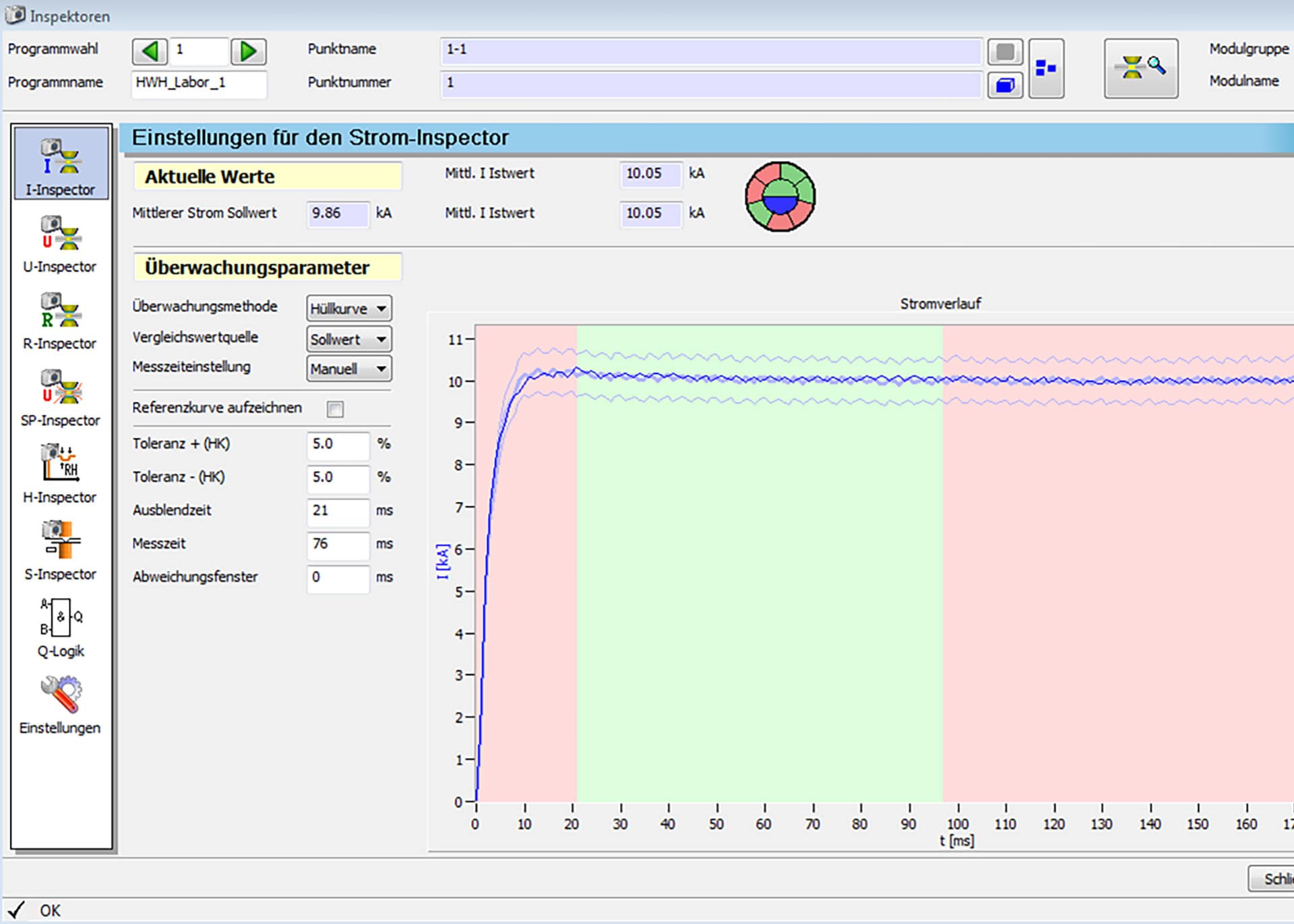
Depending on the application and welding task, we offer various optional equipment for our Genius inverters. If you need a good documentation of your welding quality, we have the right documentation tool for you. We offer to carry out documentation of components in an internal database, on a PC or server, as well as documentation of your welding data to an external database. e.g. for the spot welding task in the sheet metal area we recommend to use our IQflex system. In this system, different tools are available for each spot welding task. Extensive monitoring is already integrated.
The integrated IQR quality control regulates the current during welding as a function of the resistance curve or power curve. The aim is to control disturbance variables in the welding process. The welding time adjustment is controlled depending on the time of the resistance maximum. The most prominent time in the resistance curve is the end of the warm-up phase and the beginning of melting. From this point on, the resistance curve starts to fall again, as the contact resistance between the material is eliminated and the electrode starts to sink in. We call this point “resistance maximum”. This timing varies. It depends on the disturbance variables that have an influence on heating. Influencing disturbance variables are e.g.:
- the electrode diameter
- the conditions of subordination
- the mains voltage variations
- the force losses due to poor fit
From the moment of the resistance maximum, the up to now rising setpoint of the current from previous process information is kept at its current level with a delay. This results in a new welding power for the further course of the weld that is dependent on the interference size in each case. By programming the initial current and the steepness of the rise, called “aggressiveness”, the heating can be changed up to the resistance maximum. If, as in rare cases, this is not sufficient, the welding time can also be adjusted depending on the resistance maximum. Here, the intervention in the cycle time must be taken into account. Experience shows that variations in magnitudes of no more than ±5 ms result in robotic applications.
IQflex is the adaptive control and monitoring from the first spot weld based on the proven Genius platform. In addition to our proven IQR controller and Q-lnspector, IQflex also includes the option of the reference-guided adaptive controller IQf with extended monitoring of the weld via the new IQ-lnspector. Short commissioning times and simple operation guarantee efficient and cost-effective production. The IQflex adaptive package is specially optimized for these requirements and guarantees reliable spot welding of steel materials. The elementary process variables current and voltage form the basis for our controller. A voltage tap on the secondary side of the transformer provides a precise and reliable measurement signal from which all necessary process variables can be determined.
The actual welding gun or machine remains free of cables to ensure easy maintenance By means of the process resistance, which is recalculated every millisecond, the controller individually adjusts the welding current to the requirements of each welding spot. This guarantees a short process time since the required energy is applied in a concentrated manner. Minimizing cycle time is one of our customers’ most important criteria for using IQflex.
Benefits and advantages at a glance
- Fast parameterization through simple operation
- Reliable monitoring with our new IQ Inspector from the first spot weld.
- Documentation of all welds in the XPegasus database
- Retaining the proven IQR function – Living Industry 4.0The economy is on the threshold of the fourth industrial revolution. Driven by with safe and proven Harms & Wende products
- 100% compatibility with existing IQR parameters
- Full integration into an existing XPegasus network
- Curve display in usual Genius performance
The integrated preconditioning enables stable conditions to be established between the electrode cap and the workpiece surface at the start of the actual welding process. Regardless of whether the material used is coated or contaminated, the weld succeeds with IQflex. The IQ-lnspector monitors the quality of each weld, helping you to fully meet your customer requirements.
Applications
- Spot welding with adaptive control
- Automated production
- Use of hand-operated welding tongs
- Different combinations of materials
- different plate thicknesses
Monitoring methods
- IQ-lnspector on reference value sources
- R-lnspector (see R-lnspector]
The PQS-Ready option provides you with the integrated technical prerequisite for using lnline process monitoring for your spot and projection welding applications in the Genius system. This integration eliminates the need for an additional QUADRIGO measurement module The required PQS-Res software license for data evaluation and analysis is not part of the PQSready option and must be purchased separately. The license is protected with a license dongle. This is in the form of an SD card and is inserted into the welding controller when the software license is used.
Features of the PQS-Ready option
- Software provision of the process variables current, voltage, resistance, power and displacement in the Genius inverter for the PQS-Res software.
- Additional hardware for measured value acquisition is not required.
The “Process Data Documentation” (PPD) option gives the user the possibility to query process data from a higher-level plant PLC via the fieldbus and to save it in the plant PLC. For this purpose, the process data is provided after the welding process, which is identified by the end identifier by means of the continuation contact (FK) signal. A PC is not required for this, as the data can be queried by acyclic data exchange via the fieldbus interface.
Range of functions
- Maximum 10 parameters per welding.
- The 10 parameters can be selected from a parameter pool. The Pool parameter is described in the operating instructions.
- The process parameters are only valid until a new start signal is set for the next heatsealing point.
Requirements
- ProfiNet card G432-PNSe / G433-PNSo (without 24 V I/O)
- In addition, another EA card G201 MIO is required.
Note: The reading of welding curves is not supported yet.
Note: HWH offers a library for TIA Portal 14 / Siemens, which simplifies the implementation of PDD by blocks. Instructions for using the library’s building blocks are described in a quick reference guide.
The “Trace Tag” option is an accompanying identifier to add an external information to a weld. This gives the user the possibility to add an identifier of the welding spot to the archive data of the module via the Ethernet interface (UDP). The information can consist of max. 32 ASCII characters. This can be, for example, an order number, parts or body identification number. It is used for documentation and tracing back to the spot weld or a batch. Trace Tag (TT) is an optional feature of the Genius inverter. It requires a fieldbus connection with network functionality. Currently Profinet and EhternetlP fieldbuses are available with this function. The identifier is sent as a UDP packet from the higher-level controller to the Genius inverter. The identifier remains pending until a new packet is sent. If the inverter has been switched off, an identifier must be sent again so that the entry can be made in the archive.
Requirements
- Genius-Firmware-Version: 2.70
- XPegasus Gold: as of version 5.2.31
- UDP-capable network
- Set port numbers
- Archive configuration
With the “AMC /DCM” a control mode is available which allows a preconditioning of the material. Material pairings with different oxidation tendencies and varying contact resistance pose a challenge for the welding process.
In order to realize the welding task with the best possible quality, it may be necessary to subject the material to preconditioning.
This provides the basis for consistent spot quality in resistance welding of aluminum alloys, for example. The unique combination of adaptive preconditioning and controlled force profile has been developed by Harms & Wende specifically to meet the requirements of modern aluminum materials for the spot welding process. The AMC/DCM mode is available as an option for all GeniusHWl inverters.
Another field of application of AMC/DCM mode is welding of various functional elements
{nuts, bolts, brackets, etc.) on the components made of boron-alloyed steel 22MnB5. The well-known negative effect of the AISi coating can be effectively suppressed for such materials by using preconditioning. In addition, to contribute to process stability, the typical variation of AISi thickness can be compensated by adaptive control of preconditioning.
A conditioning current is output during the conditioning time, during this time the process resistance is measured continuously. When a previously defined conditioning threshold is reached, preconditioning is terminated and the actual current time with the set main current begins. The conditioning threshold establishes identical initial conditions for each weld to achieve consistent spot quality. Depending on the varying contact resistance, different conditioning times are achieved. If the value does not fall below the conditioning threshold, a message is output.
It is possible to use both pneumatic proportional valves and electromotive clamps. The “AMC / DCM – Mode” is configured via the user interface
The part documentation option allows the user to display an overview of all joints from all production modules that run through a part. The recorded data of the weld are saved as an archive data set. This data set contains the welding program and the part identifier. The archive records can be displayed in the Xpegasus.
Requirements
- min. XPegasus Gold
The High Speed Current option allows the user to achieve faster current rise behavior. Fast current rise times are often required, especially for projection welding. To achieve this, a fast modulation of the secondary voltage is necessary. The prerequisite is a correspondingly low-resistance secondary circuit of the welding machine and a secondary circuit voltage between 16 V- 21 V.
When welding nuts on high-strength material, a short welding time is advantageous in order to achieve a good bond between the nut and the sheet metal.
Using the example of a projection welding system with a low-impedance secondary circuit and an MF transformer with a secondary voltage of 21 V, currents of 60 kA with current rise times of 4 ms -10 ms can be achieved in practice. This allows a medium frequency system to replace a KE system. The advantage is that a wider range of products can be welded.
The application range here is between 30 kA -150 kA.
The High Speed Current option is available for the GeniusHWlxx range of MF power inverters. Inverter output currents of up to 3500 A can be achieved, depending on the power type. The possibilities of MF welding technology with high secondary voltage offer great advantages here, as very good scalability is achieved in the application.
The MMl option includes an extension of the measurement inputs by an additional plug-in module G202 in the Genius system. This module is intended for use on a welding machine for a displacement and/or force control.
The following inputs are available
- 1 x displacement measurement input -analog 0-10 V, 0-20 mA, 16 bit
- 1 x force measurement input -analog 0-10 V, 0-20 mA, 16 bit
Pathway fair entrance
- See S-lnspector
Force measurement input
The force sensor is connected to the force measurement input. The calibration as well as the parameter input for the force build-up control in the force lnspector is done by means of the XPegasus user interface, from version
6.xx. The force build-up control monitors the force just before the weld time is used at the end of the hold-off time. The force is measured and compared with the set tolerance values. If the value is outside the tolerance, an error message is output.
Features
- Strength building control
Option MM2 is an extension of the measuring inputs by an additional plug-in module G202 in the Genius system. This module is intended for use with, for example, a double-head welding system.
The following inputs are available
- 2 x displacement measurement input -analog 0-10 V, 0-20 mA, 16 bit
- 2 x force measurement input -analog 0-10 V, 0-20 mA, 16 bit
Pathway fair entrance
- See S-lnspector
Force measurement input
The force sensor is connected to the force measurement input. The parameters for the force calibration as well as the parameters of the force build-up control are entered via the XPegasus user interface, from version 6.xx, on the side of the force lnspector. The force build-up control monitors the force just before the weld time is used at the end of the hold-off time. The force is measured and compared with the set tolerance values. If the value is outside the tolerance, an error message is output.
Features
- Strength building control
Downloads